Quick Access Panel: ![]()
Ribbon: 3D Viewer - Tools - 3D Section
The 3D section panel has controls for setting up visual display of 3D models and section planes. The panel is available in the 3D Viewer mode. The commands and options of the 3D Section panel enable to customize 3D model viewing. To display parts of a model, section and gizmo use the settings located at the top of the form. It is possible to create several planes at the same time.
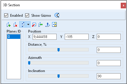
Parts of a model and section controls
On top you can find settings enabling to change display of model parts and visual elements of section control.
Option |
Description |
Enabled |
Enables a 3D model section view. When this option is activated, a 3D model part created as a result of the intersection of the model with a plane is displayed. |
Show Gizmo |
Gizmo allows moving and rotating a section plane in the workspace with the help of mouse. Gizmo matches with the selected plane in the list. |
|
When this option is activated, the model parts cut with one or several planes are displayed. When this option is disactivated, the model parts that were not cut are displayed. You may use this option when you have more than one plane and you want to cut a sector with acute angle. |
Section planes control
The toolbar has options ![]() to configure the section plane position.
to configure the section plane position.
Icon |
Name |
Description |
|
Planes ID |
List of numbers of added section planes. To change or delete s plane first select it in the list. |
|
Adds a new plane |
Adds a new plane. The new plane is added at an angle of 90 degree to one previously added. It is possible to add three mutually perpendicular planes with three clicks. The added plane goes through the geometric center of the model. |
|
Deletes the selected plane |
Deletes the selected plane. |
|
Defines a plane |
Defines a plane by the selected points on a model in one of the proposed ways. When any of the option is activated the gizmo hides. If the plane list is blank, a new plane is added, otherwise the selected plane in the list is changed. Ways to define a plane: •By three points. •By select entity. •Change the base point. |
|
By three points |
Defines a plane that goes through three planes. |
|
By select entity |
Surface - a plane tangent to the selected point on a model surface is defined. Direct edge - a plane perpendicular to an edge is defined. Circular-arc edge - a plane containing the selected circle is defined. The base point is set in the circle's center. |
|
Change the base point |
The section plane is displaced in such a way as to go through the selected point. The normal direction of the plane is not changed. |
|
Aligns the selected plane with the YZ plane |
Changes the normal direction of the selected plane. Places the plane in parallel with the YZ plane. Adds a section plane if the section list is blank. The plane goes through the geometric center of the model when it is added.
|
|
Aligns the selected plane with the XZ plane |
Changes the normal direction of the selected plane. Places the plane in parallel with the XZ plane. Adds a section plane if the section list is blank. The plane goes through the geometric center of the model when it is added. |
|
Aligns the selected plane with the XY plane |
Changes the normal direction of the selected plane. Places the plane in parallel with the XY plane. Adds a section plane if the section list is blank. The plane goes through the geometric center of the model when it is added. |
|
Changes the direction of the selected plane |
Changes the direction of the selected plane to the opposite one. |
Section plane position parameters
Option |
Description |
Position |
The group has fields to enter X, Y, Z coordinates of the selected section plane base point. |
Distance |
Specifies the distance between the selected plane and the object center as a percentage of the bounding circle radius. You may specify the value either by moving the slider or by entering it from the keyboard. |
Azimuth |
Angle in the XY plane between the X axis and the projection of the selected plane normal. You may specify the value either by moving the slider or by entering it from the keyboard. |
Inclination |
Specifies a plane inclination - angle between the Z axis and the selected plane normal. |
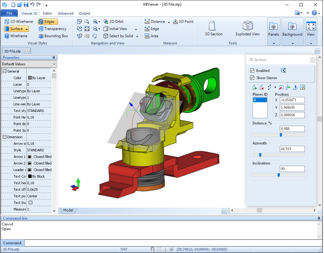
Example of a 3D model section view
Go to ABViewer