The ViewPort button allows creating ViewPorts on the Layouts.
Quick Access Panel: ![]()
Ribbon: Editor -> Draw -> ViewPort
Menu: Draw -> ViewPort
Viewports are used to arrange the drawing to be printed. They allow to set the visibility of all the drawing located on the Model sheet or only some part of it and specify the customer scale in the Layout area. Viewports can be moved, resized and their properties can be edited. For the Viewport border no to be printed it should be placed on a separate layer, which should be later switched off or forbidden to be plotted. It is impossible to add Viewports on the Model area.
Modifying a Viewport
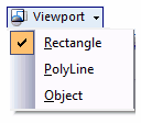
A Viewport can be created in different ways which allows to get viewports of an arbitrary shape. to specify the borders of a viewport one can use three modes which are available after clicking on the black down directed arrow:

By default the Rectangle mode is selected. The Options PolyLine and Object allow to create Wipeouts of an arbitrary shape.
Rectangle |
Adding a rectangular viewport. It is craeted like the entity Rectangle: The first point of the diagonal of the rectangle is specified, and then the second one. In the dynamic input mode you can set the width and height of the viewport. |
|---|---|
PolyLine |
Adds a nonrectangular viewport using the specified points. It is created like the entity polyline. Selecting Enter in the context menu finishes drawing and closes the contour by drawing the last segment. |
Object |
Allows to modify a viewport into a closed object, that has been added to the layout earlier. A circle, an ellipse, a spline, and a polyline, forming a closed contour can be used as an object for modification. After creating a viewport the oblect that sets its borders becomes connected with it. To create a viewport from an object 1.Create an object which will determine the borders of the viewport with the help of the drawing tools. 2.Select the mode Object from the drop down list of the tool Viewport. 3.Selet the earlier created object for modifying it into a viewport. |
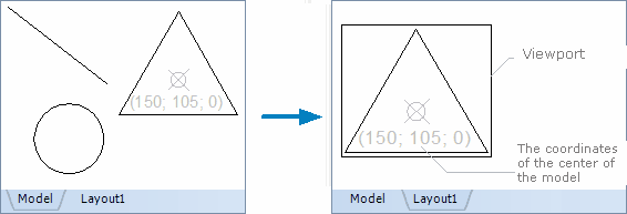
After a viewport is created all the objects which are on the Model sheet will be displayed in the specified viewport. The contents of the viewport aren't available for editing, but they can be moved within the borders of the viewport and their scale can be changed. All the changes performed in the sheet Model are displayed in the viewport.
Viewports, created with the help of a polyline or modified from an object consist of two elements: a viewport and a cutting border. The cutting border is a geometrical object, which is used to create a viewport. You can edit a viewport, a cutting border or the both parameters.
For the Viewport border no to be printed it should be placed on a separate layer, which should be later switched off or forbidden to be plotted.
Work with the Contents of a Viewport
The image in the viewport can be moved and scaled. The work with the contents of a viewport is available after its activation.
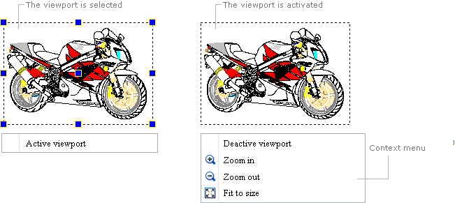
To activate a viewport left double click within the borders of the viewport or select the viewport and click on the command Active viewport in the context menu. After activation the markers of the viewport will disappear and its borders will be shown with a dashed line.

Moving |
Activate the viewport and holding the left mouse button pressed drag the cursor of the mouse in the direction where the image should be moved. |
|---|---|
Scaling |
The image can be scaled with the help of the mouse wheel or commands of the context menu when the viewport is activated. A precise scale coefficient can be specified in the panel Properties by means of the property Scale. Each viewport can have its own scale. |
To deactivate a viewport select the command Deactive viewport in the context menu or double click with the left mouse button outside the viewport.
Editing a Viewport
After creating a viewport its borders can be shifted and resized. Editing is performed with the help of the markers, which appear after a viewport is selected. The central marker serves to move the viewport without resizing it. Corner and middle markers allow to change the size of the viewport.
A viewport like other objects has a certain set of properties which are displayed in the Properties panel after a viewport is selected. Some properties are available for editing, some other ones are for information only.
Property |
Description |
|---|---|
Color |
Defines the color of the viewport. Allows to set a new color value. |
Layer |
Defines the layer which the viewport belongs to. The property contains a list of all available in the drawing layers and allows to move the viewport to another layer. |
Paper Center |
Defines the coordinates X, Y, Z of the center of the viewport in the sheet area. The values can be edited by the user. Note: Viewports created with a polyline or modified from objects consist of two objects: a viewport and a cutting border. This property shows and allows to edit the center of the viewport, without editing the coordinates of the cutting border. |
Height |
Defines the height of the viewport. The property can be edited. When the height of the viewport is changed the scale is changed proportionally in the panel Properties. |
Width |
Defines the width of the viewport. The property can be edited. |
Scale |
Defines the scale coefficient of the viewport. Each viewport has an own scale value. |
View Twist Angle |
Is the angle to the axis OX by which the contents of the viewport is rotated relative to the base point of transformation. |
View Target |
Is the base point of transformation relative to which rotation of the image in the viewport is performed. Shows the coordinates in the Model area. |
Model Center |
Is the coordinates of the center of the model image, shown by the viewport :  |
Front Clip Plane |
Sets the front cutting plane. |
Back Clip Plane |
Sets the back cutting plane. |
Disable |
Switches the visibility of the image in the viewport on or off. |
Go to ABViewer